Pneumatic Conveying Overview
Pneumatic conveying is a method of bulk solids handling utilizing pressurised gas (carrier phase) to move solid particulates (transported product) along pipelines. Transporting materials down pipelines is not a new concept with people as far back as the bronze age 4000BCE using clay pipes to carry waste away with water in what would be the first effective sewer systems. More recently water has been used to transport products in a wide range of industries, this is known as hydraulic transport. However, if the product is affected by water in any way this method is unviable. Thus, in the 1950’s a German man named Gasterstadt began experimenting with moving solid particles down pipelines using air as the carrier fluid. His experiments utilised a high air mass flow rate with little pressure requirement to suspend the particles in the pipeline. This would later become known as Dilute phase/ Lean Phase pneumatic conveying. Gesterstadt’s research inspired students from Japan and companies in the United States to conduct their own research. This research resulted in another method of pneumatic conveying to be discovered, dense phase conveying. Dense phase conveying is the polar opposite of its lean phase counterpart in that it utilizes high pressure and low gas volumes to push the product along the bottom of the pipeline. Since then large amounts of research have taken place in an effort to make these two key methods of conveying as efficient as possible.
At present pneumatic conveying features, heavily in a wide range of process industries, moving the solids between locations on site. A few examples of these industries include; chemical, aggregates, food, pharmaceutical, agricultural and manufacturing etc. The two main alternative methods of bulk solid handling that pneumatic conveying is competing against are belt conveying and screw conveying. The pros and cons for each method are as follows:
Pneumatic Conveying
Belt Conveying
Screw Conveying
Pros
- Flexible routing
- Prevents contamination of product
- Short-long run length
- Low maintenance
Pros
- Short-very long run
- Very low energy consumption
- Minimal material degradation
Pros
- Low energy consumption
- Low material degradation
- Prevents contamination of products
Cons
- High power consumption
- High material degradation (in lean phase)
- Easy to get wrong
Cons
- Difficult to move around bends
- Higher maintenance requirements
- Contamination potential
Cons
- Very short-short run
- High maintenance requirements
- Difficult to move around bends
Whilst pneumatic conveying certainly has its benefits a poorly designed system can consume two or three times the energy of an efficient system. Despite this the pneumatic conveying market continues to grow. This is validated by research from 2014 showing an expected to market rise to $30.67 Billion by 2022.
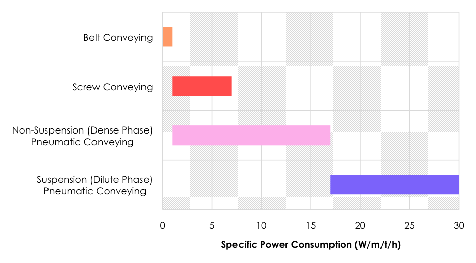
Research conducted by the Wolfson centre and compiled in 2015 quantify the power consumption of the four key methods of bulk solid handling (belt conveying, screw conveying, dense and lean phase conveying). As can be seen in Figure 1 lean phase conveying is the most inefficient method of conveying with the specific power consumption being between 17-30 W/m/t/h. Whereas compared to belt conveying which has a specific power consumption between 0-2 W/m/t/h.
Specific Power Consumption of Bulk Solids Handling Methods

Figure 1 Specific Power Consumption of Bulk Solids Handling Methods
This is reflected by the research suggesting that, in 2014, Pneumatic conveying systems accounted for approximately 4% of the UK’s energy requirements. This value is expected to rise with the growth in the Pneumatic conveying market. In an ever-changing climate, it is important to ensure that energy is utilised and not wasted. Ensuring that pneumatic conveying systems operate as efficiently as possibly could greatly reduce the energy consumption for huge numbers of industrial plants around the world. To do this pneumatic conveying and the physics of multiphase flows need to be understood.
Pneumatic Conveying Modes
To understand pneumatic conveying, the two key methods of pneumatic conveying must be clearly understood. The two key methods of pneumatic conveying are lean phase (otherwise known as dilute phase or suspension phase) and dense phase (also known as non-suspension phase).

Figure 2 Pneumatic Conveying Modes of Flow
Lean Phase
Lean Phase systems operate by suspending the particles in the air stream to move it along the length of the pipeline. The key component of a lean phase system is the mass flow of the air. As a side effect of moving product in this mode there is a pressure requirement due to pressure loss caused from gas-wall, particle-wall, particle-particle interactions etc that all effect the pressure loss in a system. Nonetheless, lean phase systems rarely require more than 1BarG to move the product unless moving very large distances. Solids Loading Ratio (SLR) is the ratio of solid mass over the gas mass. Lean phase systems will operate between 2-25 SLR, i.e. they can move 25 times the amount of solid mass to gas mass in the most efficient systems. However, this is largely dependent on material, nearly all materials will convey up to an SLR10. The benefit to this mode of conveying is that there are no limitations of material. The downside to this method of conveying is that due to the requirement for high gas mass flow rate the minimum conveying velocity for lean phase systems tends to be around 15m/s. This can pose a problem to brittle products or products that deform under relatively low temperatures (such as plastic pellets). It becomes even more of a problem when Eq.1 is factored in and as the pressure falls the velocity increases. Thus, in a system that starts at 15m/s with a pressure drop of 1BarG you would expect velocities around 30m/s at the outlet. This is another reason why higher pressures are not used in lean phase systems as a 4BarG system would see an outlet of approximately 75m/s in a single size pipeline.
Dense Phase
Dense Phase systems operate at much lower air velocities to their lean phase counterparts. This is due to the fact that dense phase systems do not suspend the particles in the air stream when conveying them. Dense phase systems are typically associated with high pressure requirements; however, this is dependent on conveying distance and material. It is true that dense phase conveying methods require higher pressure per metre than lean phase due to the larger shear forces incurred by moving product along the bed of a pipeline. Nonetheless global pressure loss for a lean phase or dense phase system largely depends on conveying distances and materials. There are two key sub categories of dense phase pneumatic conveying; fluidized dune flow (also known as moving bed flow) and low velocity slug/plug flow.
Fluidized Moving Bed/ Dune Flow
Fluidized flow is a method of conveying which operates by trapping gas particles amongst fine powders turning them from static solids into fluid-like entities. The key factor behind this working high level of air retention by having approximately 40% of the particles less than 30μm for this to work. Fluidization is a balancing act, to convey a fine powder using moving bed flow the minimum velocity must be over 3m/s approximately as anything less than this and the aerodynamic drag is too low to move the particles. Above this value and the particles begin to exhibit fluidic behavior. Increasing the velocity too high however to approximately 10m/s for fine powder and the particles will become suspended moving it into a lean phase mode of conveying. The key benefit to this method of conveying is it can move SLR’s up to 250 allowing for the same amount of air as a lean phase system 10x the product to be moved. The key downside is the requirement for only fine material to be moved with it.
Slug/Plug Flow
Slug/Plug flow is a method of dense phase conveying that works for air permeable materials. I.e. materials that have a very narrow size distribution (mono-sized particles). According to the Wolfson centre at Greenwich University materials where the particle size d90 can be no larger than 2.5x the d10 value [4]. Materials such as plastic pellets, pills or uniform food substances classify as air permeable. The gaps between the particles allow air to pass through the material, even if the line is completely full. The mono-sized particles thus get pulled through the pipe due to differential pressure in front/behind the plug and aerodynamic drag on the particles. This method requires very low air velocities to move the product, typically around 3m/s. This has the benefit that unlike lean phase conveying the particle are not smashed into the bends at high velocities. The downside is that unlike its dense phase counterpart it is limited to an approximate SLR of 40. Whilst it is an improvement on lean phase SLR the significantly lower velocities mean that the solid throughput is usually equal to or less than lean phase conveying.
All of these methods of conveying have their benefits and limitations. Lean phase systems however are the most common accounting for approximately 70% of industrial pneumatic conveying.
Positive vs Negative Pressure Systems
Whilst both lean phase and dense phase systems can operate in positive and negative pressure. In lean phase systems both positive and negative pressure systems are utilized. Both systems offer their own benefits and drawbacks. The most common type of feeder for positive pressure systems are rotary valves one of the big drawback to these valves is the rate of air leakage dependent on differential pressure above and below the valve, thus limiting them to approximately 1BarG in most scenarios. This attribute of rotary valves means that positive pressure systems can provide product to multiple locations without losing air/pressure, however if feeding from multiple positions the rotary valve air leakage will accumulate and losses will be considerable. Vacuum systems are inverse allowing to pick up from multiple locations but deposit in a single location.
Another consideration when specifying either a pressure or vacuum system is that to achieve the same air velocity a larger pipe diameter is required for the vacuum line. This is due to the fact that a vacuum line picks material up at atmospheric conditions and the gas expands as it moves down the line, a pressure system picks material up with compressed gas which expands to atmospheric as it moves down the line. Thus, the larger volume of gas at the inlet of a vacuum system requires a larger pipe size to attain the same minimum conveying velocity as a pressure system.
Other factors worth noting are that in most positive pressure systems the conveying pickup point is after the compressor, i.e. the gas will be much hotter in a pressure line (unless pre-conditioned). Also, the receiving hopper/silo for vacuum systems need to be pressure rated to handle the negative pressure whereas none of the vessels need to be pressure rated in positive pressure systems.
When it comes to dense phase systems they avoid the issue of rotary valve air leakage by batch conveying using a blow tank. Dense phase vacuum systems are uncommon. This is due to the pressure range available in vacuum. In positive pressure, a system can reach in excess of 7BarG, whereas vacuum systems are limited to a maximum of 1Bar vacuum. Thus, whilst dense phase vacuum system is an option they are limited and only used over very short distances. Most dense phase systems therefore operate in positive pressure.
Pneumatic Conveying Equipment
Pneumatic conveying systems can vary quite dramatically, but the basic principle is the same. A method of supplying air/pressure, a method of introducing solid product and a method of separating the product/ air.

Figure 3 Typical Positive Pressure Lean Phase System

Figure 4 Typical Negative Pressure Lean Phase System

Figure 5 Typical Negative Pressure Lean Phase System

Figure 6 Typical Positive Pressure Dense Phase System
Compressor

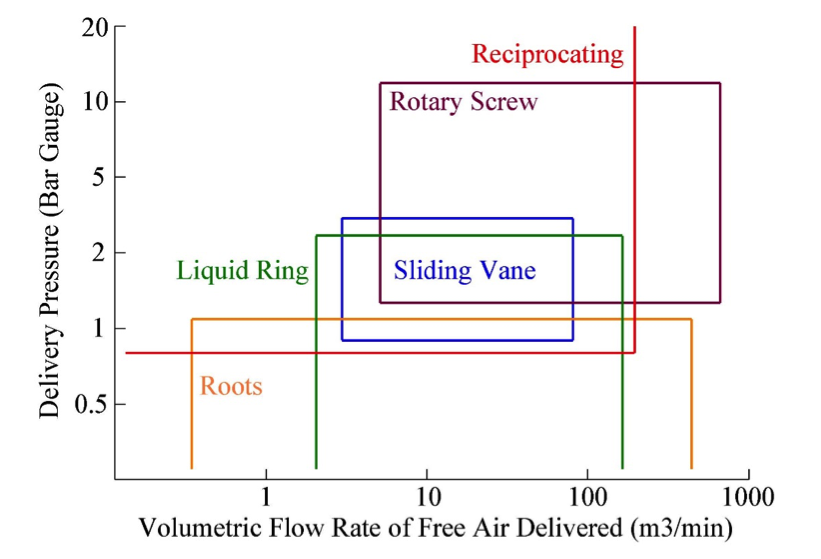
The compressor is largely dependent on the mode of conveying. For example, lean phase systems operate predominantly up to 1BarG pressure and a wide range of volumetric flow rates. The sunburst diagram below shows how compressors can be classified. There are three main considerations when specifying a compressor for a pneumatic conveying system. when specifying a pneumatic conveying line compressor is that the compressor supplies dry clean air. Thus, reciprocating compressors are not often used in pneumatic conveying. When liquid ring and screw compressors (oil cooled) are utilised, the air has to be dried and filtered first.
Another consideration when selecting a compressor is that the volumetric flow rate does not change too greatly with pressure. This is key to ensuring that the air speed does not drop below the minimum conveying velocity due to pressure fluctuations in the pipeline. Positive displacement compressors are far superior to aerodynamic compressors for pneumatic conveying systems, as the volumetric flow rate exhibits minimal changes with pressure change, unlike aerodynamic compressors were the volumetric flow rate can change anywhere between greatly with pressure changes.
The final consideration is that the compressor can achieve the duty required of it, this is where Figure 8 features. The most common compressors for lean phase systems are roots type blowers the reasons for this are as follows; there is no oil in contact with the air being moved ensuring the air is clean, they can maintain volumetric flow rates despite pressure fluctuations, they are offered in a wide range of flow rates and pressures up to 1BarG (in line with most lean phase systems).
The rotary screw compressor is the most common compressor offered with dense phase systems for the same reasons as the roots type blower however the rotary screw will typically operate between 1-10BarG (dependant on whether it is dry screw or oil cooled) unlike the roots type blower.

Figure 8 Compressor Performance Comparison
Feeder
The feeder much like the compressor is largely dependent on the mode of conveying. There are three key considerations when specifying a feeding device. The first consideration is pressure in the line and above the feeder. For example most lean phase systems will operate at a maximum of 1BarG and will feed from atmosphere thus there is a differential pressure of 1Bar across the feeding device. Therefore, either a blow tank or a rotary feeder would be suitable for this application. Venturi feeders and gate valves cannot withstand high pressures commonly. Screw feeders can handle the higher pressure however if there is a large pressure gradient the air will simply escape past the screw.
The second consideration is whether the material is being batch or continuous conveyed. In this instance the screw, rotary valve and Venturi can operate in either batch or continuous whereas blow tank and gate valves will only offer batch in a single line. The third consideration is feed rate control and for this the screw feeder is the only truly accurate method.
In lean phase systems, rotary feeders are the most common used method of feeding as they; are cheap, can withstand differential pressures of around 1BarG (before air begins to leak considerably from the pressurised line past the product to atmosphere), and they also offer reasonably accurate federate control. Whereas dense phase systems commonly utilise blow tanks, this batch method allows material to be introduced to a tank which is pressurised, once at pressure the conveying line is opened and product is moved down the line. Blow tanks can operate continuously with twin tanks so that one tank is feeding and another is loading. However, this can become expensive. Screws will commonly be utilised with both of these methods; rotary feeders and blow tanks to offer accurate control over product flow rate.
Gas/ Solid Separation
Gas solid separation is a key process within pneumatic conveying. The main method of separating a gas and solid is by using a filter that allows the air to pass through and prevents the solid particles. The key design point of a filter unit is ensuring that the filter is sized appropriately. This is based on the volume of air passing the filter and the filter velocity. The filter velocity commonly being around 1.1m/min. This means that for a system moving 0.15m³/s of air with a filter velocity of 0.0183m/s the minimum required filter area would be 8.2m². Ensuring that the area is such that the filter velocity it equal to or less than 1.1m/min prevents particles from embedding themselves in the filter material.
Whilst this is a key factor behind specifying a filter unit it is not the only factor, material being conveyed, if the product is explosive, particle sizes, and cleaning method are all factors.
There are two key methods of filter cleaning, mechanical cleaning (shaker) and pneumatic cleaning (reverse jet filter). Reverse jet filter units are the most common, as they are considered to be the most effective for cleaning the filter elements. They work by releasing pressurised gas through nozzles to force particles out of the filter elements from the inside. A common cause for a system failing is the filters being blocked, this makes it difficult for the air entering the system to leave, this intern causes the pressure to rise. If the pressure rises in a system the velocity at the inlet will drop and could therefore see it fall below minimum conveying velocity, it could also cause the system to shut down due to pressure switches or relief valves. A clean filter unit should only cause 15mBar of pressure loss on a system.

